
Thesis Review: The Mechanics
My thesis was focused on the animating of roaming animatronics and as such led to a animation driven mechanical design. To focus on the animation of the character, the mechanisms were designed to be as minimal as possible. Referencing existing robotics platforms that have similar form factors. With a character height of 82cm, robots such as the Toddlerbot and Judy Hopps animatronic were referenced. Both figures utilize directly driven joints that are simpler in design and functionality. The character is bipedal but has legs that differ from traditional humanoid robots such as Atlas or the G1. Robots that had leg designs based on animals such as Cassie and Spot are more akin to the design of the character and proved to be more effective reference material.
The final mechanical design of the figure, has 3 degrees of freedom (DoF) per leg, 3 DoF per arm, 3 DoF in the body, and 3 DoF in the head, totaling 18 DoF altogether. The figure was primarily built using 3D printed components that were threaded to ensure a proper fit. The exceptions to this were the head shell, which was vacuum formed, and the hooves, which were cast in urethane foam. The vacuum formed head shell was for lighter weight as 3D printed shell proved too heavy. The hooves were cast in urethane foam skin as dampeners and grips when the figure takes a step.
Arms
The process of creating the mechanical design for the upper body relied on various iterative steps that, with time, became a cohesive mechanical system. The first was to get an arm to work. The initial test consisted of using 3 Dynamixel motors, model XL430-W270-T. The design took inspiration from the Judy Hopps animatronic that Disney showcased in 2023. The three were arranged in a manner that suits realistic movement of the arm for the character. Opting for the following movements
Elbow Bend
Arm Raise
Shoulder Rotate
These movements in this chained alignment allow for a wider range of movement while keeping within the scale of the character, though with little tolerances. There was an early concept that included a fourth movement, an arm rotate, that would have added another link in the chain to create a wider array of poses for the arm. That being said, the existing tight tolerances did not allow for all four movements, as a result, priority went to the movements that added the most range. The elbow was the area with tighter tolerances, the actuator fit the space of the elbow of the shell very tightly requiring small protrusions for the motor to fit properly. These changes affected the silhouette of the character minimally, if not at all. Had the silhouette been drastically changed, the actuator would need to be replaced with one of a smaller form factor or the sculpt of the character would need to altered. The former being the preferred option as, at this step in the process, going back to edit the sculpt could create discrepancies in the shells, if some were created before this edit.
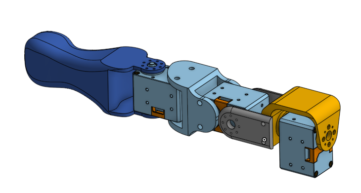
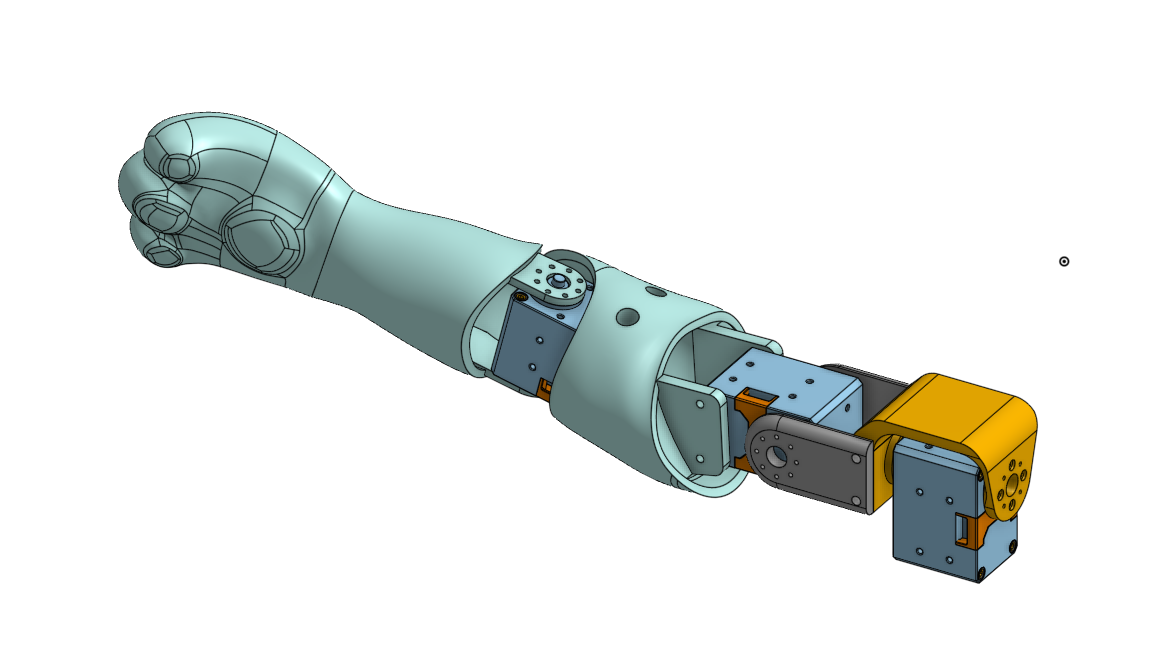
In many animatronics, the mechanical parts, structural parts, and shells are three distinct sets of components. The mechanics should be capable of assembly on the structural parts and function with and without the shells. For the arms, given the form factor of the motors and the minimal space, it was approached with a monocoque design, having the shells act as structural parts. This minimized the number of parts necessary to assemble the arm. Requiring only five 3D printed parts and three actuators.
Upper Torso
The upper torso consisted of three movements; a body tilt, body bend, and a body twist. The body functions differ from the arms in that they function with linkages as opposed to direct drive. This choice was made for the body twist in efforts to avoid placing an axial load on the actuator and allow a central "spine" to make the body more structural. If the body twist was direct driven, then it would make the point of failure would be the attachment point of the servo horn. This connection is not the most secure as it would only have a point of contact of around one square inch. The "spine" solution will have contact surface across multiple components in different layers of the body keeping the animatronic together more effectively. The range for this function is lower because the size of the effector requires a small change in the angle to change the silhouette of the figure.
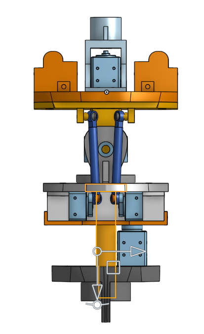
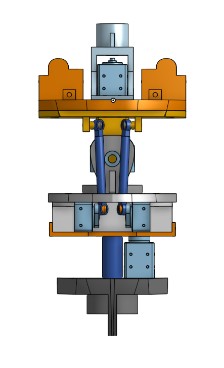
The body tilt and bend are accomplished via a dual actuator drive with the effector sitting on a U joint component. This allows two axes of freedom and provides a compound movement without stacking the functions. Earlier versions had the body bend function without the tilt and was driven by a single actuator. However, during a test animation, the Bend forward cause a moment that exceeded the capabilities of the actuator. A solution could have been limiting the range, but it was pushing the actuator too close to stall. In this instance, the actuator used is the XM430, which stalls at 4.1 Nm. By increasing the number of actuators, it would facilitate the body bend and open the possibility for experimenting with the body tilt which was ultimately permanently added to the design.
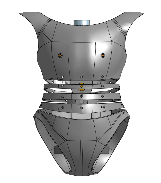
The body structure and shells were done separately. Structure consists of seven plates that screw together. They were separated in such a way to facilitate the manufacturing primarily through 3D printing but would allow for Machining if it were to be necessary. The shells were 3D printed that mount to the plates with screws and attach to each other with magnets. The magnets were selected to be strong enough to hold together when moving but removable without the need to apply an excessive force. The shells for the rib cage were designed to maintain the shape of the character and prevent any fur that would be incorporated later.
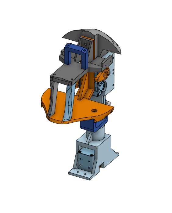
Head
The head mechanics are similar in the body in that they are driven by two motors with a 3D printed u-joint as the point of freedom. In contrast to the body, the head has the actuator stacked on top of each other to accommodate the space. As well as having the actuators above the point of the rotation as opposed to having the point of rotation above it. This does make it so that the weight of the actuators is now included in the load that it is moving, but because the head is significantly lighter than the body, that additional weight from the motors does not heavily impact its performance. The actuators for these functions were XL430-W270-T.
The shells for the head were accomplished differently than the rest of the body. While the shells across the figure are 3D printed, they had presented a challenge for the head. Given the size of the head, a 3D printed shell would have been way too heavy. Instead, vacuum-formed shells were utilized through the process of creating a plaster buck from molding and casting, seen in Figure. The process began with 3D printing the ideal buck for the back of the head as well as the front. Vacuum-forming is accomplished by heating up plastic to a malleable degree, pressing it against the form and sucking out all the excess air to shape it. PLA, the most used material for 3D printing is not ideal to use for vacuum-forming because the heat causes the surface of the 3D print to bubble and become distorted negatively affecting the formed material. The 3D printed buck is molded using brush-on silicone and a plaster jacket to keep the shape. Both molds are filled with plaster to take a plaster buck as plaster does not react negatively to heat from the vacuum former. The vacuum-formed shells are made of PETG, a thermoplastic of a 1.5 mm thickness. Despite the very thin wall when PETG is in complex curvature such as that of the character, it becomes sturdier and significantly lighter compared to a 3-4 mm 3D printed shell. The shells are mounted onto the base of the head using standoffs that are of the curvature of the head based on the 3D model. Because this form of manufacturing is slightly deviated from the exact model, it needs to be edited slightly to ensure a proper fit which requires trimming excess material of the vacuum-formed shells.
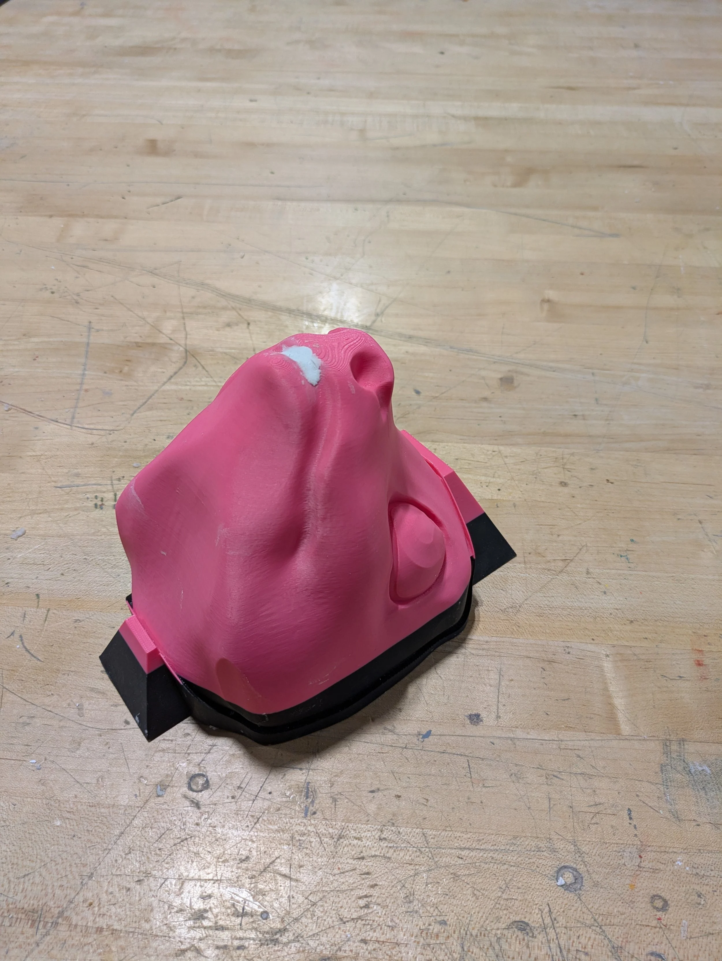
3D printed buck
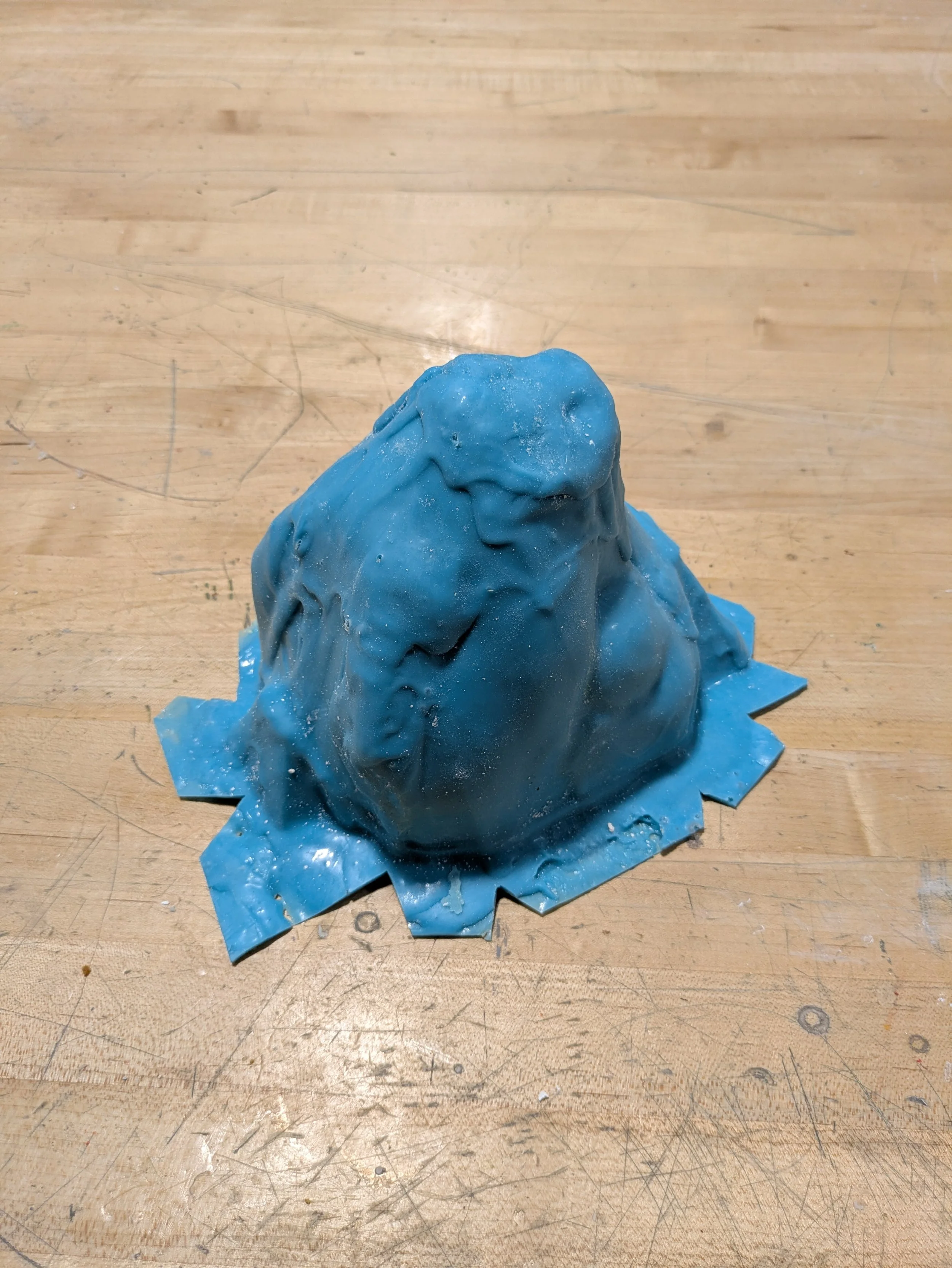
Brush-on silicone layer to catch details
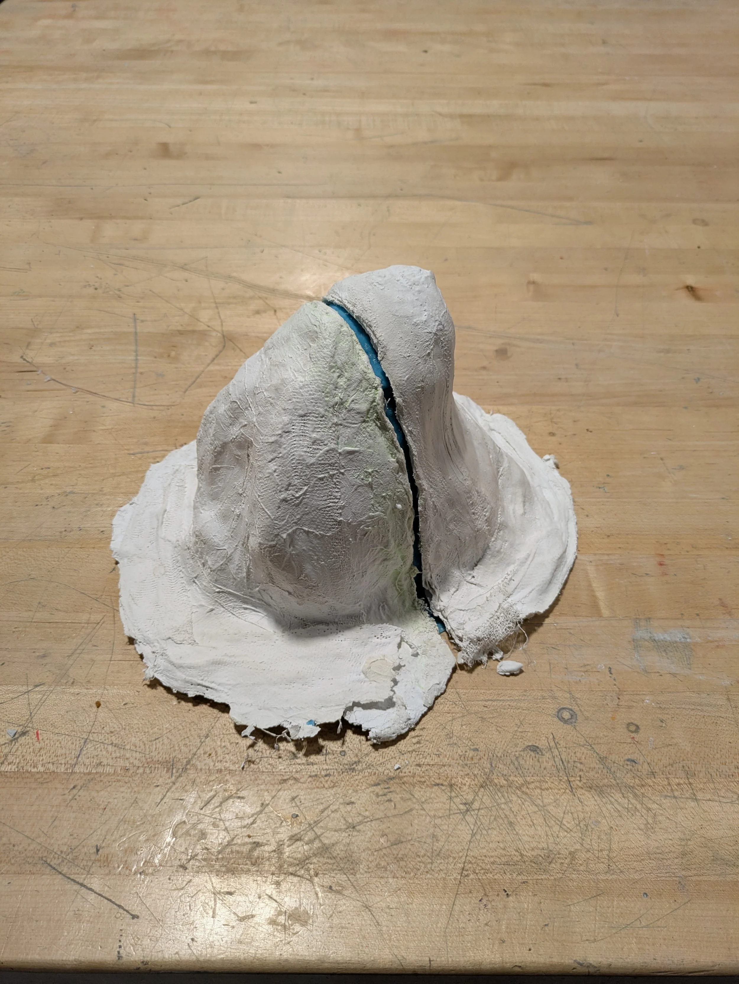
Plaster jacket layer
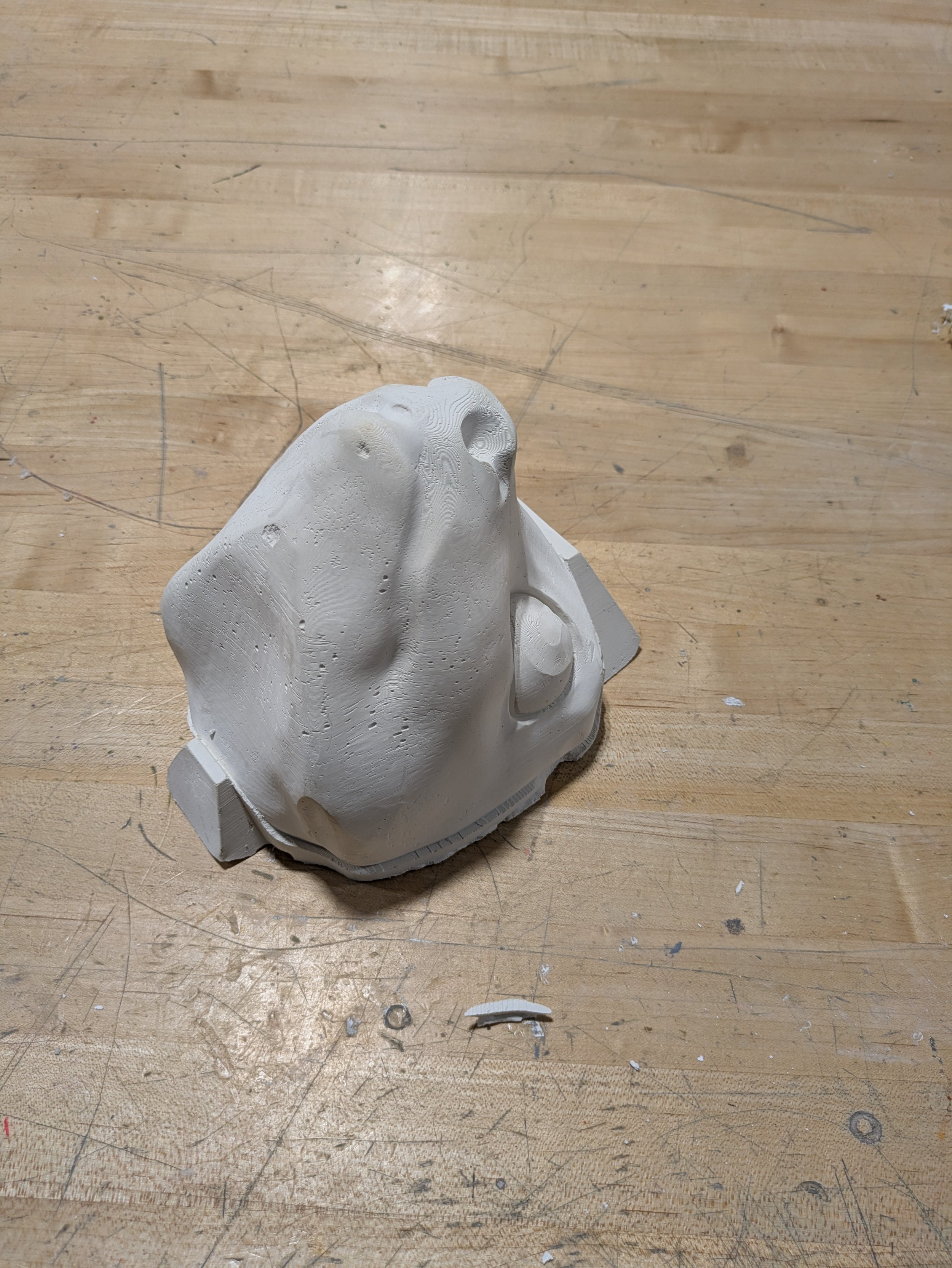
Plaster cast of positive
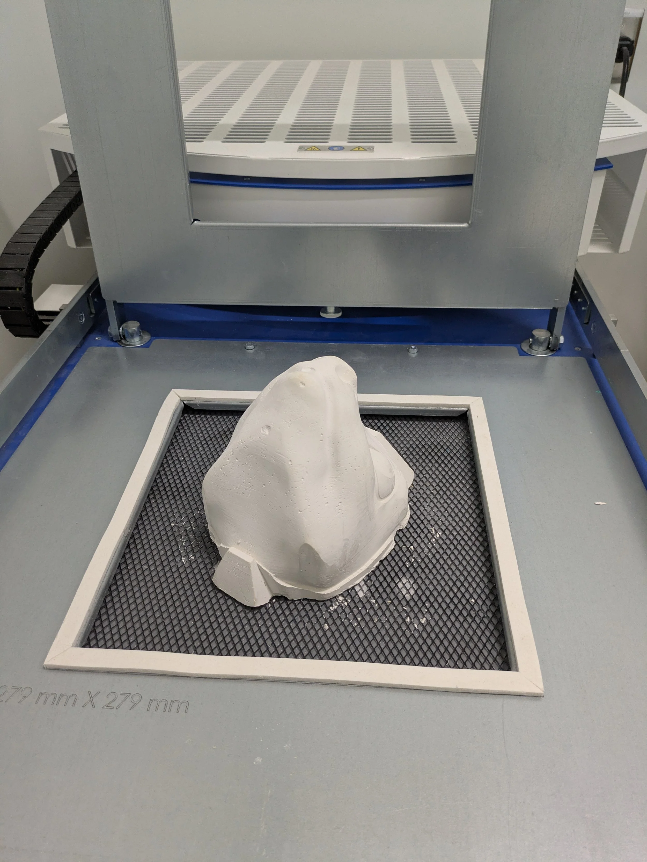
Buck in Vacuum-form machine
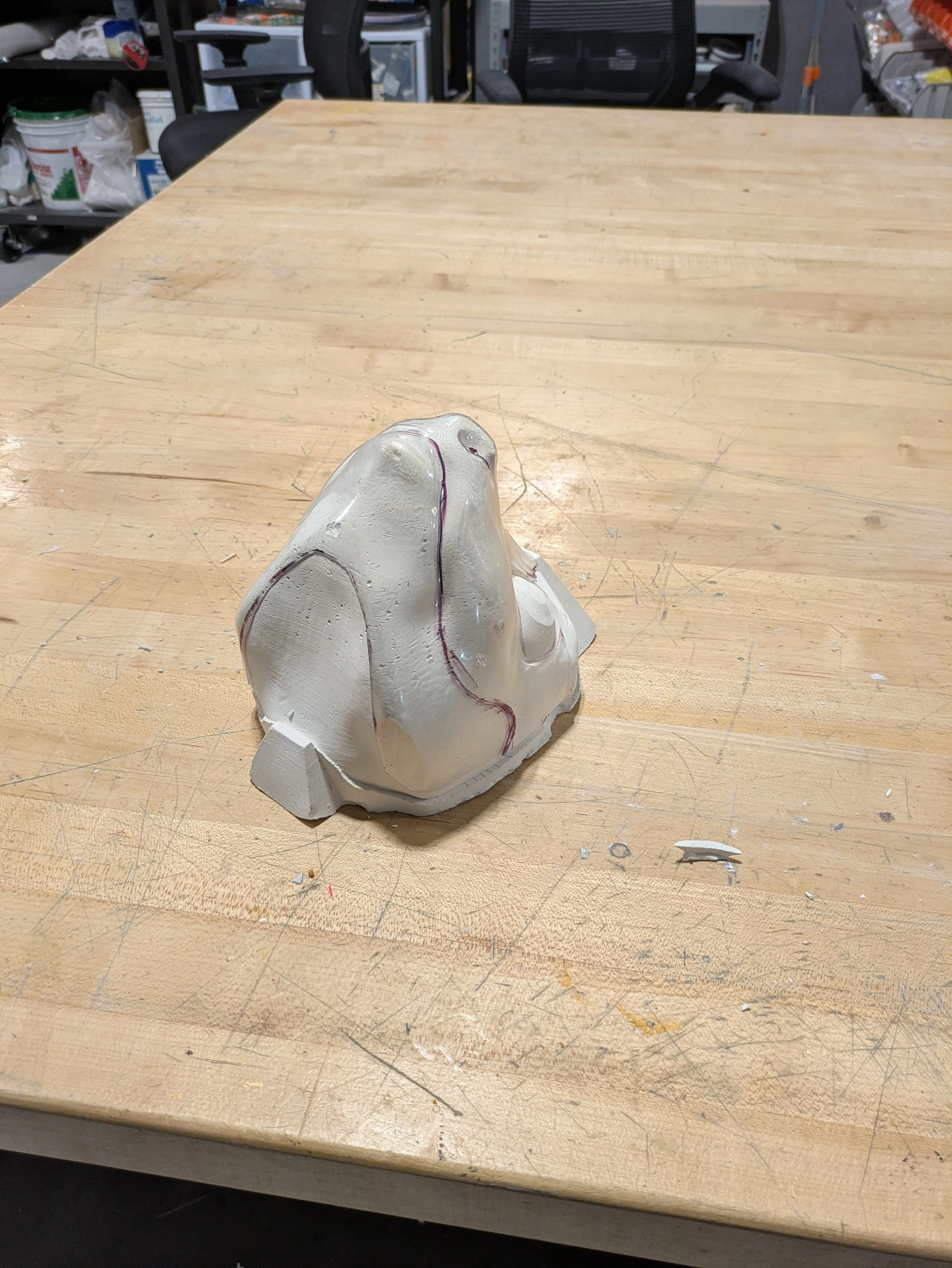
PETG shells on buck post-processing
The neck turn functions by using a D-shaft that extends from the chest cavity of the figure into the head, pictured in figure. The removable head component has a slot that the D-shaft fits into. To prevent the weight of the head from loading the actuator axially, the head is supported by a stand that is attached to the torso. The XL430-W270-T actuator used for this function is rated to support more than the weight of the head, but I was concerned that the weight could cause friction during use.
Legs
The legs are designed with compliance as a goal. Compliance is a system's ability to react to external stimuli. In an animatronic, these reactions add a layer of minute movements that add character through a principle of animation called “Follow through.” According to The Illusion of Life: Disney Animation, follow through refers to having parts of the character not stop suddenly and move as if they follow the laws of physics and then return to their resting position. This is usually added in the animation stage of development but adding mechanical parts that can aid in the application of this will facilitate the animation later. In animatronics, it is very common to see it in pneumatics because air is compressible and when momentum or sudden movement act upon the system, the air in the pneumatic cylinders react with small compression. This presents a challenge for this thesis, in that pneumatics are not an option because they require air tanks and can be very loud. For a show that intends to be mobile and has a field of view of, if not near, 360 degrees, the only option available is electronic actuators. While electronic motors don't have compliance inherently, there is a way to create the illusion of compliance. The first is through PID controls, a software solution, and the other is through springs a mechanical solution.
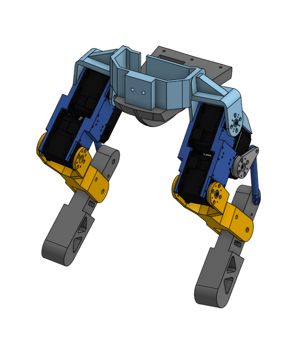
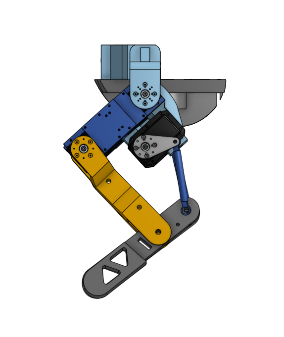
To implement the springs, the leg needs to be generally modeled to determine where it can be attached. The functions that would be motorized would be the hip forward, knee bend, and ankle bend. The Dynamixel MX-64 actuators drove these functions. Chosen for their high torque output, these motors will be supporting the weight of the figure with some assistance but with a stall torque of 6Nm across 6 actuators this should be sufficient for the figure. The knee and hip are driven directly, seen above, while the ankle bend is driven by a linkage. This linkage proved to be the most effective place to implement a spring for compliance. There were a few tests to compare using an extension spring or a compression spring. The extension spring was effective at responding to movement but needed to be a stiffer spring to be able to also act as a linkage. The compression spring, in this case a shock, was too stiff or did not fit the existing form factor of the figure. It was decided to use the extension springs.
Like the body, the shells for the legs are separate components that attach to a standoff bracket. One of the additional design goals for the legs involved ensuring there was enough room to allow air flow to prevent the actuators from overheating. The legs will be experiencing the most force acting upon them which will result in the motors consistently having a high output torque, which will lead to a high current draw. A consistently high current draw will raise the temperature of the actuator, and if the actuator gets too hot, it will shut down. The large volume of the legs aided in this task, but there is still a concern for the hip actuator, has it has the least amount of surface exposed to air. In test runs, the actuator has not shown any signs of overheating and the temperature feedback returns below the max temperature tolerance of the actuators.
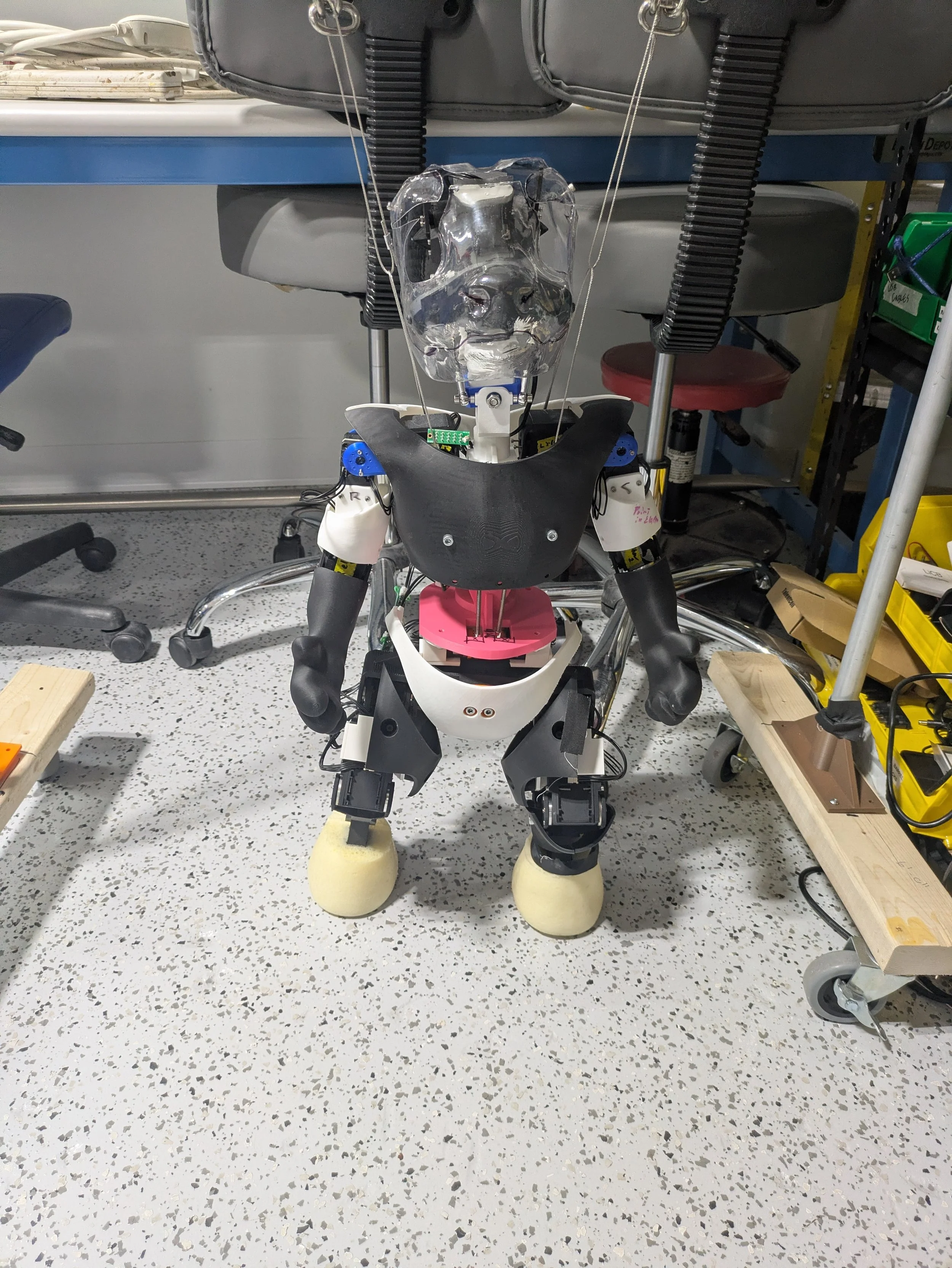
With the mechanics, there comes a variety of safety concerns. The motors are all rated with high amounts of torque and in any animation where they could be moving quickly or suddenly, can run the risk of injury if anyone gets in the way. There are a few measures to take with these actuators; they possess what are referred to as PID controls. This would require some time for tuning, but the approach would be to tune the controls, mainly the Proportional and Derivative control, to a degree that would create a "spongey" response when it encounters an obstacle of any kind. This would help minimize any damage the character could cause, but it's not a perfect solution. Pushing the derivative value too high would negatively affect the animations because it would cause them to become too 'loose" and appear unintentional or haphazard. The real solution to blunt force injury risk is to limit how close the character would get to the audience. Keeping the figure at least 2-3ft away from the closest audience member would be sufficient. The safety concerns in regard to heat are addressed in the motors themselves; they shut down when they get too hot. A preventative measure in the design is to limit the amount of contact on the motor to allow heat to dissipate while ensuring a secure mechanical attachment.
My thesis has concluded but development for this character will be continuing. There are a few edits that would like to after the demonstration keep up with updates on the project page here.